


The microprocessor was born
In 1971 two companies, both in the USA, introduced the world to its future by producing microprocessors. They were a young company called Intel and their rival, Texas Instruments.
The microprocessor and its offspring, the microcontroller, were destined to infiltrate every country, every means of production, and almost every home in the world. There is now hardly a person on the planet that does not own or know of something that is dependent on one of these devices. Yet curiously, so few people can give any sort of answer to the simple question ‘What is a microprocessor?’ This, and ‘How does it work?’ form two of the starting points for this book.
Let’s start by looking at a system
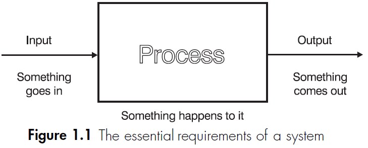
The word ‘system’ is used to describe any organization or device that includes three features. A system must have at least one input, one output and must do something, i.e. it must contain a process. Often there are many inputs and outputs. Some of the outputs are required and some are waste products. To a greater or lesser extent, all processes generate some waste heat. Figure 1.1 shows these requirements.
The word ‘system’ is used to describe any organization or device that includes three features. A system must have at least one input, one output and must do something, i.e. it must contain a process. Often there are many inputs and outputs. Some of the outputs are required and some are waste products. To a greater or lesser extent, all processes generate some waste heat. Figure 1.1 shows these requirements.
A wide range of different devices meets these simple requirements. For example, a motor car will usually require fuel, water for cooling purposes and a battery to start the engine and provide for the lights and instruments. Its process it to burn the fuel and extract the energy to provide transportation for people and goods. The outputs are the wanted movement and the unwanted pollutants such as gases, heat, water vapour and noise.
The motor car contains other systems within it. In Figure 1.2, we added electricity as a required input to start the engine and provide the lights
The motor car contains other systems within it. In Figure 1.2, we added electricity as a required input to start the engine and provide the lights


and the instruments but thereafter the battery is recharged by the engine. There must, then, be an electrical system at work, as in Figure 1.3, so it is quite possible for systems to have smaller systems inside or embedded within them. In a similar way, a motor car is just a part of the transport system.
A microprocessor system
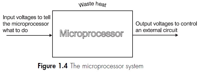
Like any other system, a microprocessor has inputs, outputs and a process as shown in Figure 1.4. The inputs and outputs of a microprocessor are a series of voltages that can be used to control external devices. The process involves analysing the input voltages and using them to ‘decide’ on the required output voltages. The decision is based on previously entered instructions that are followed quite blindly, sensible or not.
Like any other system, a microprocessor has inputs, outputs and a process as shown in Figure 1.4. The inputs and outputs of a microprocessor are a series of voltages that can be used to control external devices. The process involves analysing the input voltages and using them to ‘decide’ on the required output voltages. The decision is based on previously entered instructions that are followed quite blindly, sensible or not.
His and hers garage door opener
Here is a little task that a simple microprocessor can solve for us. When the woman arrives in her car, a light signal is flashed at the sensor and only her garage door opens. When the man arrives home, his car flashes a light signal at the same sensor but this time his garage door opens but hers remains closed.
The cars are sending a different sequence of light flashes to the light sensor. The light sensor converts the incoming light to electrical voltage pulses that are recognized by the microprocessor. The output voltage now operates the electrical motor attached to the appropriate door. The overall scheme is shown in Figure 1.5.
In the unlikely event of it being needed, a modern microprocessor would find it an easy task to increase the number of cars and garages to include every car and every garage that has ever been manufactured. Connecting all the wires, however, would be an altogether different problem!

The physical appearance of a microprocessor
A microprocessor is a very small electronic circuit typically 1⁄2 inch (12 mm) across. It is easily damaged by moisture or abrasion so to offer it some protection it is encapsulated in plastic or ceramic. To provide electrical connections directly to the circuit would be impractical owing to the size and consequent fragility, so connecting pins are moulded into the case and the microprocessor then plugs into a socket
A microprocessor is a very small electronic circuit typically 1⁄2 inch (12 mm) across. It is easily damaged by moisture or abrasion so to offer it some protection it is encapsulated in plastic or ceramic. To provide electrical connections directly to the circuit would be impractical owing to the size and consequent fragility, so connecting pins are moulded into the case and the microprocessor then plugs into a socket

on the main circuit board. The size, shape and number of pins on the microprocessor depend on the amount of data that it is designed to handle. The trend, as in many fields, is forever upward. Typical microprocessors are shown in Figure 1.6.
Terminology
Integrated circuits
An electronic circuit fabricated out of a solid block of semiconductor material. This design of circuit, often called a solid state circuit, allows for very complex circuits to be constructed in a small volume. An integrated circuit is also called a ‘chip’.
Microprocessor (µp)
This is the device that you buy: just an integrated circuit as in Figure 1.6. On its own, without a surrounding circuit and applied voltages it is quite useless. It will just lie on your workbench staring back at you.
Microprocessor-based system
This is any system that contains a microprocessor, and does not necessarily have anything to do with computing. In fact, despite all the hype, computers use only a small proportion of all the microprocessors manufactured. Our garage door opening system is a microprocessor-based system or is sometimes called a microprocessorcontrolled system.
Microcomputer
The particular microprocessor-based systems that happen to be used as a computer are called microcomputers. The additional circuits required for a computer can be built into the same integrated circuit giving rise to a single chip microcomputer.
Microcontroller
This is a complete microprocessor-based control system built onto a single chip. It is small and convenient but doesn’t do anything that could not be done with a microprocessor and a few additional components. We’ll have a detailed look at these in a later chapter.
MPU and CPU
An MPU is a MicroProcessor Unit or microprocessor. A CPU is a Central Processing Unit. This is the central ‘brain’ of a computer and can be (usually is) made from one or more microprocessors. The IBM design for the ‘Blue Gene’ supercomputer includes a million processors!
Remember:
- MPU is the thing
- CPU is the job.
Micro
The word micro is used in electronics and in science generally, to mean ‘one-millionth’ or 1 x 10⁻⁶. It has also entered general language to mean something very small like a very small processor or microprocessor. It has also become an abbreviation for microprocessor, microcomputer, microprocessor-based system or a micro controller – indeed almost anything that has ‘micro’ in its name. In the scientific sense, the word micro is represented by the Greek letter µ (mu). It was only a small step for microprocessor to become abbreviated to µP. Some confusion can arise unless we make sure that everyone concerned is referring to the same thing.


